return to How to Build and Run the GEK Gasifier
Assembly Instructions for the GEK 3.0-TOTTI
Table of Contents:
I) Introduction
II) Tools Needed
1. Gas Cowling
2. Downdraft Reactor Insert
3. Cyclone
4. Auger
5. Pyrocoil and Pre-heating Bucket
6. Flex Hose Gas Tube
7. Mechanical Fuel Level Sensor
8. Gas Out Tube to Filter Housing
9. Hopper
10. Filter Housing
11. Ejector Venturi System
12. Manometer
I) Introduction
The gas cowling, reactor and hopper bolt together into a single vertical assembly. The filter housing bolts to the flange on the top of the cyclone in a vertical assembly which is then attached to the reactor via the gas outlet flange of the cyclone. The ejector venturi system and the burner assembly is attaches on the top of the filter housing.
All these parts are pictured below. This is what you should have received with the Level IV kit, or built via your own efforts.

While assembling the various vessels, be sure to remember these common standards used throughout the GEK kit:
-All metal to metal flange connections require clay weather stripping two rows thick, as air tight sealant.
-When tightening bolts follow same pattern as tightening lug nuts on your car. Stagger tightening, don't go around in order. This will keep a good air tight seal.
II) Useful Tools for Assembly:
- 1/2" wrench or crescent wrench
- 1/2" sockets for socket wrench or (ideally) cordless drill/impact driver and drill to socket adapter
- Two extenders for sockets (to reach reduction bell nuts)
- X/X" wrench or socket or crescent wrench (for leg nuts)
- Two from the following list (for plumbing):
- >2" Monkey Wrench
- Channel locks
- Vise
- Utility knife
- Allen (hex) key set (for stirrer motor)
- Flathead screwdriver
1. Gas Cowling assembly
a) Attach bottom plate
- Use ceramic gasket clay, lay it on the bottom flange of the reactor. this will cover your bolt holes so you will need to ream them out with something, a screw driver or a round file works good. it is fiberglass so wear a mask or do it outside. after you have the bolt holes in the tape, apply a bead of the high temp mortar on top of the ceramic gasket clay.
- Lay bottom plate on so bushing for ash grate assembly is on the outside of the unit.
- Bolt on with 5/16 bolts


b) Attach legs
-Turn Cowling upside down. Slide legs over posts, tighten bolts.


c) Add ash port lid.
- While the gas cowling is upside down, place two rows of clay weather stripping onto cowling around circumference
of ash port hole, on the inside of the bolts. Screw on wing nuts, hand tight.
-Turn upright.
d) Insert ash rotary grate
-Remove turning handle from ash grate, place spacer in the bottom of the cowling, so its on top of the 1" hole.
-Slide ash grate into cowling,through spacer, grate side up.
-Reach under cowling and screw on turning handle.


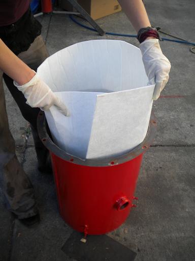
e) Insert Insulation
- Be sure to wear gloves, the insulation is currently of fiberglass material.
- Fold the insulation material to the outer edge of the inside of the gas cowling.
- It will sit above the bolt heads that are welded inside for the rocket legs, and the top of the insulation will line up with the bottom of the square gas outlet.
-The stainless steel insulating jacket will go into the gas cowling up against the fiberglass insulation, line the hole in the insulating jacket with the 1/2 inch bung on the outside of the gas cowling. (*picture to be added).
-Note: If you are upgrading to add the stainless steel insulation to a previous version of the GEK, you may need to trim the edges of the grate enough so that the stainless steel insulation will fit in between the gas cowling and the grate. We have changed the grate dimension to account for this spacing in the middle of our v3.0 shipments.
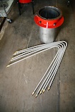
2. Downdraft Reactor insert assembly
a) Attach gas lines
- Turn insert upside down.
- Tighten one gas line into elbow coupling.
- Bend clockwise, around the outside of the next coupling, continue around to the second coupling
then bend down and start wrapping clock wise and down around insert. Keep wrapping until its
obvious which attachment it goes to in the mid flange.
- Bend a 90 degree angle about four or five inches from the end of the gas line and screw it onto the
attached coupling.
- Repeat process until all five gas lines are installed.
- Make sure not to overlap lines, they should all fit without crossing.
- Turn reactor right side up.


b) Assemble Reactor Insert and Gas Cowling
- Apply ceramic gasket clay to top flange of cowling. again you will need to ream out the bolt holes through the ceramic.
- Slide Reactor Insert into gas cowling.
- Align Reactor Insert and the gas cowling's bolt holes so that the lighting inlet is at the front of the
gas cowling. It will line up with the 1/2" close nipple in the cowling.
- Tighten nuts and bolts around flange.


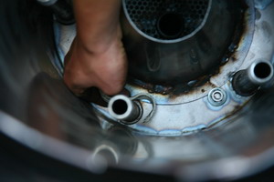
c) Install 1/2" by 6" long Pipe Nipples
- Screw in 1/2" pipe nipples into threaded couples inside the reactor insert on the bottom plate.

d) Install Reduction Bell
- Put two lines of high temp mortar around the circumference of the bottom plate of the reactor to the inside of the bolt holes.
- Put ceramic gasket clay on bottom (under side) of reduction bell base plate, so the high temp mortar and ceramic clay will create a seal.
- Put 11'' hourglass reduction bell inside reactor
- Place washers and nuts on bolts. tighten.
-Note: We have recently upgraded to an 11'' hourglass reduction bell. This was to support increased flow rates through the reactor. The 11''hourglass reduction bell does not need the tar fence. The bottom opening to the reactor was also widened to accommodate for the 11'' bell; the new reactor will still fit in the existing gas cowling.


e) Insert Air Inlet Nozzles
- Place a ring of clay weather stripping around the base of the pipe nipple.
- Rub a piece of weather strip into threads at the top of the pipe nipple, this will help secure air inlet
nozzles.
- Slide air inlet nozzles over pipe nipples and push into ring of weather stripping.
- Screw 3/8" caps on to the air inlet nozzles. This creates a more direct flow for the air.
- The cap of the nozzle will tend to fit on the inside of the reduction bell. Orient nozzle so it points in between adjacent two nozzles. - Once all installed, they will make a five sided star, all pointing to the center of the reduction bell opening. It is important that the nozzles are centered to ensure symmetrical reaction.


f) Ignition Port
- Assemble the ignition port with the 7'' plumbing nipple.
- Screw 1/2" elbows onto both ends of the 7" nipple. align them so they are facing in opposite directions of one another. on one of the elbows, screw in the 3" nipple. once assembled, it will look like a "L"
- Slide the 3" nipple through the lighting port (the port that extends about 1/4" into the reactor). The 7" nipple will lie along the inside of the inner vessel of the reactor and the elbow at the bottom will be right next to one of the air inlet nozzles.
- Be sure to seal around the port with clay weatherstripping to prevent air leakage.


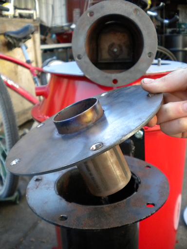
3. Cyclone
a) Attach Cyclone to Gas Cowling
- Place fiberglass tape on the square flange of the cyclone with a bead of high temp mortar to ensure a seal.
- Hold cyclone up so that both square flanges match, install nuts and bolts. Tighten. Be careful not to bend the flange.
- Place brown rubber weather stripping on both, top and bottom of the cyclone insert plate (plate with 3" tube welded in the center).
- Place cyclone tube plate into the cyclone, with the longer end of the tube facing downward.
- Place the cyclone tube inside the cyclone. (Note: if you are upgrading, this cyclone tube is different than the original cyclone tube of the base unit).
- Remember to add clay insulation to the top of the cyclone flange (not pictured).

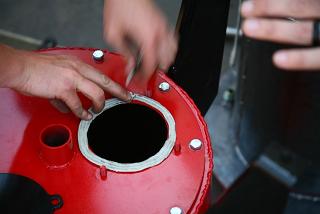
b) Attach Mason Jar
- Place ceramic gasket clay on the inside of the lid, ensure seal.
- Put plate with 1" close nipple into mason jar lid ring, nipple up.
- Screw onto jar.
- Screw into 1" coupling at bottom of cyclone.

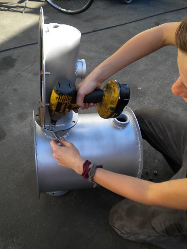
4. Auger
- Align the bolt holes of the auger and the auger motor.
- Use a lock nut with the securing bolt, tighten. Make sure it is secure enough so as not to come loose during operation.
- Seal drying bucket flange with white clay insulation included in the kit before attaching the auger motor.
- Insert the auger motor and auger assembly into the drying bucket. Use 5/16'' bolts to secure.

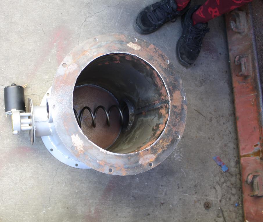
5. Pyrocoil and Pre-Heating Bucket
a) Attach Pyrocoil to Doghouse Lid
- Place insulating clay around the flange of the drying bucket.
- With 5/16'' bolts, fix the doghouse lid to the drying bucket flange. Note: The 1.5 inch coupler on the Pyrocoil should be lined up in the same plane of the 1.5 inch coupler on the drying bucket for correct orientation.
- Place insulating clay around the bottom of the drying bucket and bolt the bottom lid.


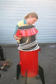
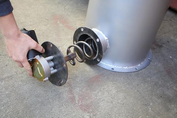
b) Orient assembly and attach to base unit
- Be sure to place the fiberglass tape insulation material on the flange of the reactor (not pictured)
- Lift the assembly onto the base unit. Orient the opening at the bottom of the drying bucket with the top of the cyclone.
- Bolt slots to support the lid and drying bucket assembly.

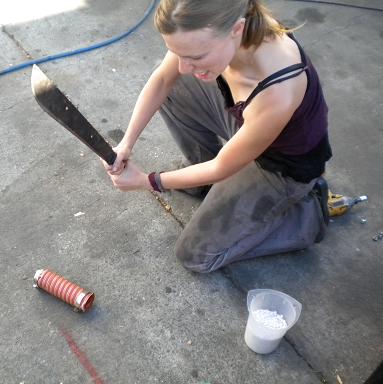
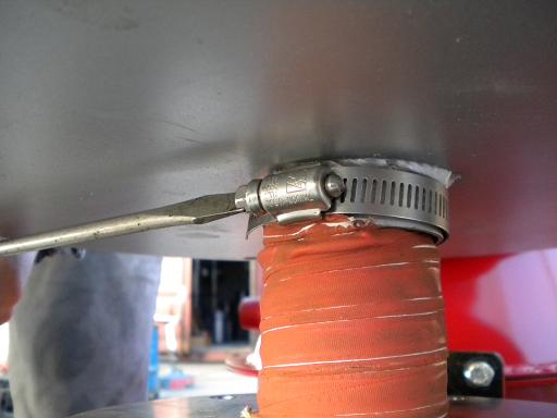
6. Flex hose gas tube
- If needed, shorten the gas tube (with proper cutting tools) to fit between the cyclone tube and the drying hopper connection.
- Tighten hose clamps.

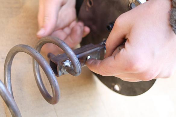
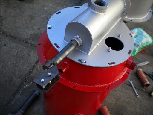
7. Mechanical Fuel Level Sensor
- The mechanical fuel level sensor will attach to the end of the 3/4" x 5" nipple on the doghouse lid.
- Attach the plunger to the end of the rod. Tighten the set screw.
8. Gas Out ube to Filter Housing
- Attach the 1.5 x 8'' black pipe nipple to the 1.5" elbow.
- Attach assembly to the 1.5'' female coupler of the drying bucket.

9. Hopper
- Be sure to add the ceramic gasket clay insulation onto the top flange of the drying bucket.
- Bolt the hopper drum from the underside with 5/16 inch bolts.


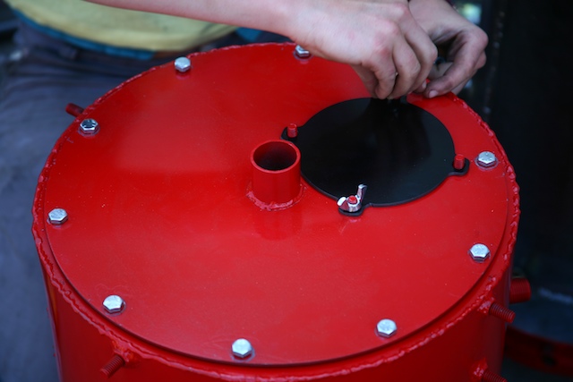
- The hopper's lid is assembled as a puff lid which will release any pressure build up in the hopper
- Use the black rubber weather stripping to ensure a seal on the hopper lid.
- Place the 1.5'' bolts through each of the four holes in the hopper, use a lock washer and a nut to secure it to the hopper drum.
- Hook the shorter end of the spring to the bolt and hold it in place by using a washer and a second nut. Repeat 4x.
- Pull the spring up to clamp down the hopper lid on four sides. Note: This replaces the need for the standard black ring for the drum.


10. Filter Housing
- To attach the filter housing to the gas outlet of the drying bucket, bolt the threaded adapter to the bottom of the filter housing using 5/16 bolts, after sealing the connection with the white insulating clay included in the kit.
- There are two grates that will go with the filter, one has stand-offs that will hold the filter media up off the bottom where the gas enters the filter.
- Filter media around 1/8th inch in diameter has worked the best. We have used charcoal from the ash grate, with the fines sieved out.
- Note: Do not use sawdust or any material will burn at low temperatures. Doing so will possibly result in pyrolysis or ignition of the filter media.
- Place a finer material over the top of your media to prevent any from exiting into the gas stream, we typically use stainless steel wool.
- Place the second grate on top of the packed filter bed to secure the media.
- Install the brown weather stripping around the lid of the filter before attaching it with 5/16 bolts. The reusable brown weather stripping comes with the kit.


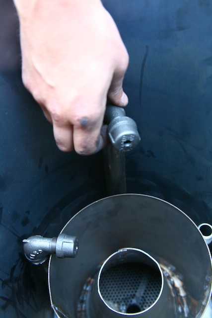
11. Ejector Venturi Assembly and Swirl Burner
- Assemble the ejector venturi assembly as shown. Be sure to tape the threads.
- The cross of the assembly screws directly on top of the filter housing.
- Attach the swirl burner to the end of the ejector assembly.


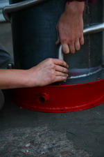
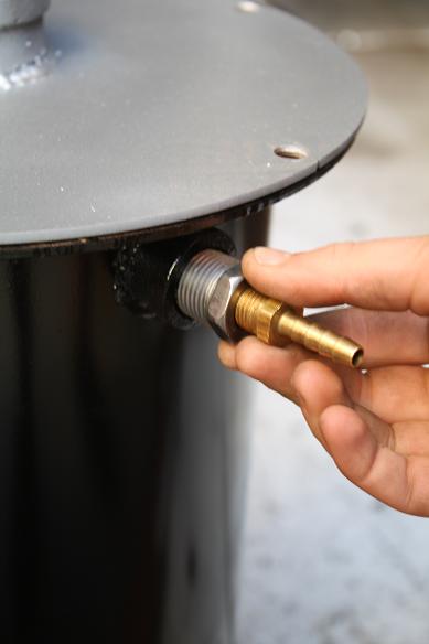
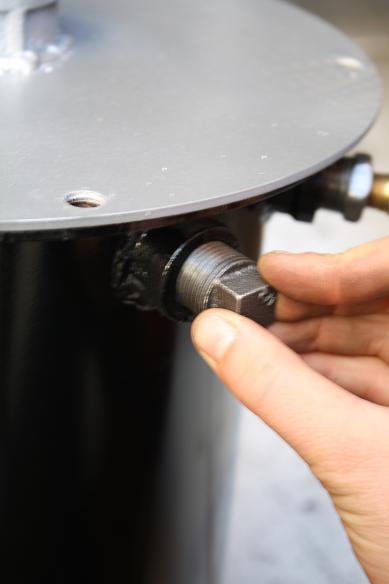
12. Manometer
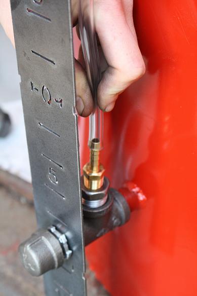
- Locate the 1/2 inch male nipple that is welded onto the outside of the cowling. This will be considered the front of the GEK.
- Thread on the 1/2" tee, (see image below) screw in 1/2 close nipple at the end of the tee.
- Screw in the 1/2 inch to 3/4 reducer on the top of the tee, put 1/4" brass barb in reducer.
- Place the manometer face plate onto the close nipple and let the top of its bracket lay underneath the flange of the gas cowling. The 5/16'' bolt that holds the reactor to the gas cowling will also hold in place the bracket of the manometer at this point. Do not put the bracket of the manometer in between the reactor and the gas cowling's flanges. This will cause leaking.
- Thread the lock nut on to the 1/2" close nipple in cowling, and place a black cap on to the end . This port can also be amended to use for a thermocouple. A thermocouple in this port will clear the bottom of the reactor and a temperature reading at the bottom of the reduction bell can be taken from this point.
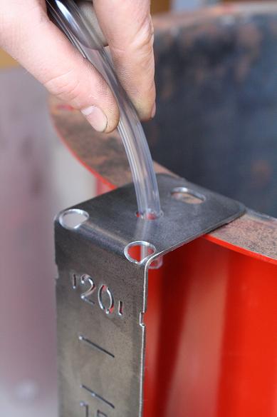
- Insert one of the clear tubes into the middle hole of the manometer bracket, feed it down through to the brass barb at the bottom.
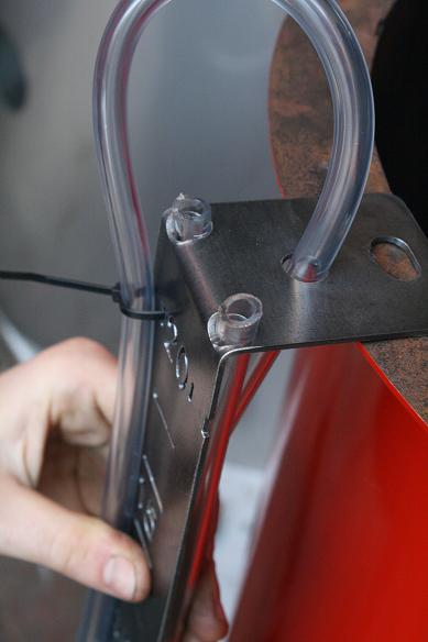
- The other end of the clear tube will follow along the front of the manometer face plate, loop at the bottom, and its end will barely poke up through the hole on the left. This is the reactor pressure manometer.
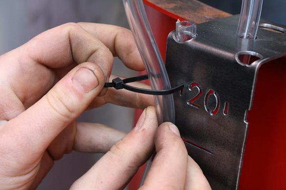
- Loop the zip tie through the manometer and around both parts of the clear tube, one piece in front and one behind.
- The filter manometer will be on the right. Start with the tip at the right hole on the manometer face plate bracket, feed it down behind the manometer, create a loop at the bottom and bring it up in front of the manometer face plate. Secure with zip ties, as before.
- Thread in the 1/2 inch to 3/4 inch reducer into one of the ports at the top of the filter housing (there are two). Thread in the brass barb into the reducer. The long end of the tube for the filter manometer connects to this brass barb.
- Notice that there are two more ports on the filter housing. Place two plugs into these ports. These two extra ports can be used for gas sampling, wet scrubbing and recycling systems, temperature, or pressure ports.


return to How to Build and Run the GEK Gasifier


Comments (0)
You don't have permission to comment on this page.