The Pre-Heating Auger and Pyrocoil are the last two additions that make up the Tower of Total Thermal Integration of the GEK v3.0.
Refer to the first Assembly Page to build the main unit of the GEK v3.0.
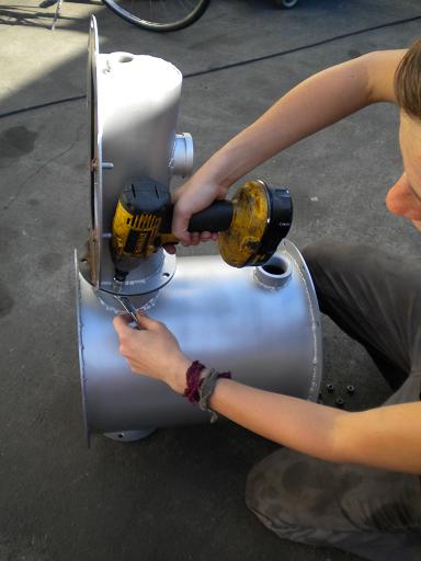
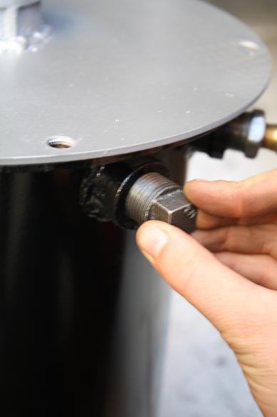
1. Auger:
-Align the bolt holes of the auger and the auger motor.
-Use a lock nut with the securing bolt, tighten. Make sure it is secure enough so as not to come loose during operation.
-Seal drying bucket flange with white clay insulation included in the kit before attaching the auger motor.
-Insert the auger motor and auger assembly into the drying bucket. Use 1/2 in bolts to secure.

2. Pre-Heating Auger Only:
a) Attach Drying Bucket to Doghouse Lid
-Place insulating clay around the flange of the drying bucket.
-With 5/16 inch bolts, bolt the Doghouse Lid to the drying bucket flange. Note: The 1.5 inch coupler on the Doghouse Lid should be lined up in the same plane of the 1.5 inch coupler on the drying bucket for correct orientation.
-Place insulating clay around the bottom of the drying bucket and bolt the bottom lid.


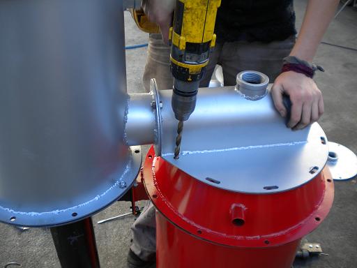
b) Orient assembly and attach to base unit
-Be sure to place the fiberglass rope insulation material on the flange of the reactor (not pictured)
-Lift the assembly onto the base unit. Orient the opening at the bottom of the drying bucket with the top of the cyclone.
-Bolt slots to support the lid and drying bucket assembly.
-Align the slots with the reactor's flange. Notice that the two smaller holes near the drying bucket will need to be drilled out with a 5/16 or 3/8 inch drill bit.


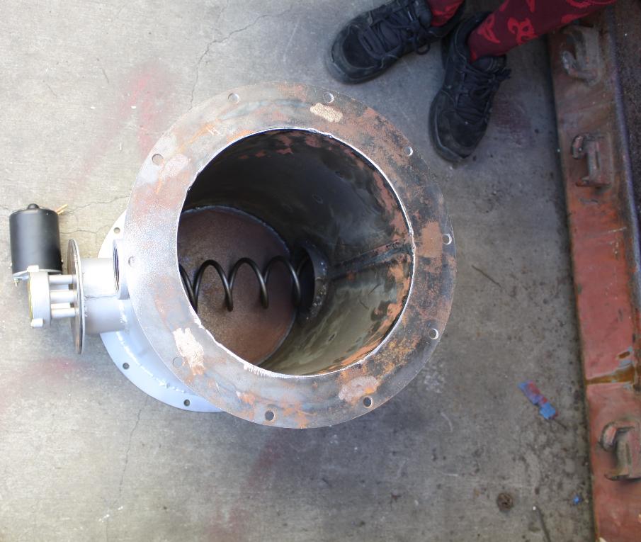
3. Pyrocoil and Drying Bucket
-Follow the steps above including insulation of flanges with clay and drying bucket assembly.
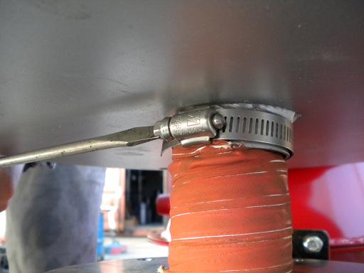
4. Attach flex hose gas tube
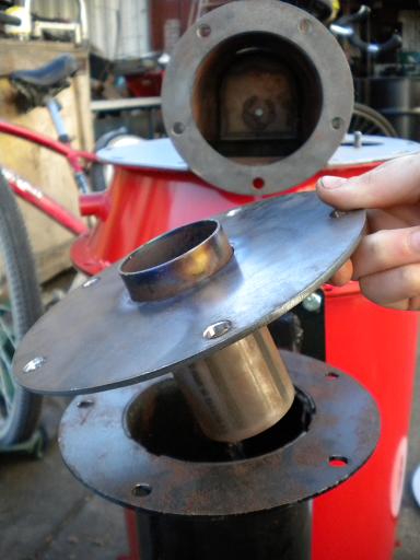
-Place the cyclone tube inside the cyclone. (Note: if you are upgrading, this cyclone tube is different than the original cyclone tube of the base unit).
-Remember to add clay insulation to the top of the cyclone flange (not pictured).
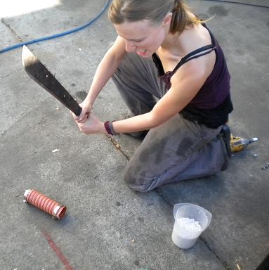
-If needed, shorten the gas tube (with proper cutting tools) to fit between the cyclone tube and the drying hopper connection.
-Tighten hose clamps.

5. Auger
-Align the bolt holes of the auger and the auger motor.
-Use a lock nut with the securing10/32 bolt, tighten. Make sure it is secure enough so as not to come loose during operation.
-Seal drying bucket flange with white clay insulation included in the kit before attaching the auger motor.
-Insert the auger motor and auger assembly into the drying bucket. Use 5/16 in bolts to secure.


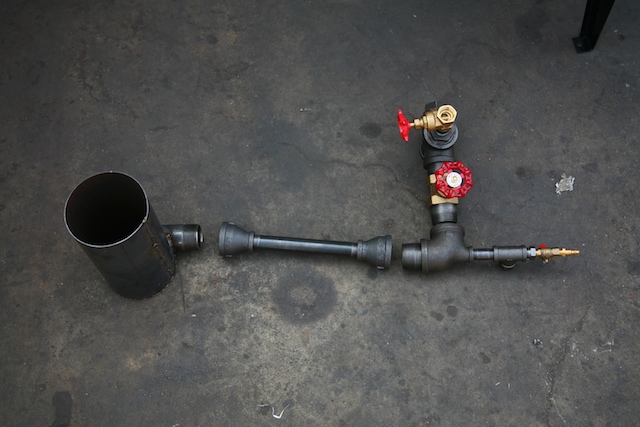
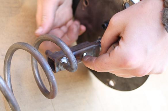
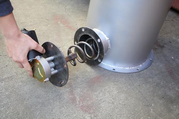
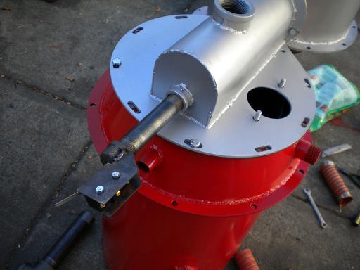
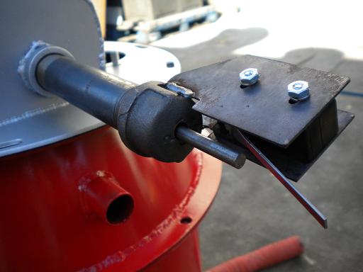
6. Mechanical Fuel Level Sensor
-The mechanical fuel level sensor will attach to the end of a 3/4" x 5" nipple.
-Feed the plunger through the cap of the mechanical sensor.
-Attach spring. (*picture of inside assembly needed)
7. Gas out tube to Filter Housing
-Attach the 1.5 x 8'' black pipe nipple to the 1.5" elbow.
-Attach assembly to the 1.5'' female coupler of the Drying Bucket.

8. Hopper
-Be sure to add the clay insulation onto the top flange of the Drying Bucket.
-Bolt the Hopper drum from the underside with 5/16 inch bolts.
-Add insulating clay and attach the lid to the top of the Hopper.

-The Hopper's lid is assembled as a puff lid which will release any pressure build up in the hopper
-Use the black rubber weather stripping to ensure a seal on the hopper lid.
-Place the 1.5'' bolts through each of the four holes in the hopper, use a lock washer and a nut to secure it to the hopper drum.
-Hook the shorter end of the spring to the bolt and hold it in place by using a washer and a second nut. Repeat 4x
-Pull the spring up to clamp down the hopper lid on four sides. Note: This replaces the need for the standard black ring for the drum.
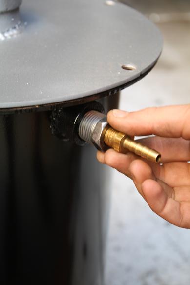
9. Filter Housing
-To attach the filter housing to the gas outlet of the drying bucket, bolt the threaded adapter to the bottom of the filter housing using 1/2 inch bolts, after sealing the connection with the white insulating clay included in the kit.
-Place a plug in the 1/2'' opening at the bottom and one of the two 1/2'' openings at the top of the filter housing.
-Attach the 1/2-3/4 reducer with the brass barb to one of the two openings at the top of the filter. This barb will connect with the clear tube for the manometer to give a pressure reading for filter life.
-There are two grates that will go with the filter, one has stand-offs that will hold the filter media up off the bottom where the gas enters the filter.
-Filter media around 1/8th inch in diameter has worked the best. We have used charcoal from the ash grate, with the fines sieved out.
-Note: Do not use sawdust or any material will burn at low temperatures. Doing so will possibly result in pyrolysis or ignition of the filter media.
-Place a finer material over the top of your media to prevent any from exiting into the gas stream, we typically use stainless steel wool.
-Place the second grate on top of the packed filter bed to secure the media.
-Instal the brown weather stripping around the lid of the filter before attaching it with 1/2'' bolts. The reusable brown weather stripping comes with the kit.


10. Edjector Venturi
-Assemble the ejector venturi referring to the picture below.
-The small nozzel will face down through to the swirl burner attached downstream.
-Attach the whole assembly to the filter housing by the open end of the 1.5'' T to the 1.5'' thread on the filter housing.