3. Cyclone and Filter
(Note: We have recently updated to a 16 gallon drum filter, If you have the eariler version click HERE)
a) Attach Cyclone to Gas Cowling
- Place fiberglass tape on the square flange of the cyclone with a bead of high temp mortar to ensure a seal.
- Hold cyclone up so that both square flanges match, install nuts and bolts. Tighten. Be careful not to bend the flange.
- Place brown rubber weather stripping on both, top and bottom of the cyclone insert plate (plate with 3" tube welded in the center).
- Place cyclone insert plate, tube side down, into cyclone.
- Place the filter on top of cyclone and align bolt holes.
- Bolt the filter housing on top of the cyclone flange, using the 5/16" bolts. These extend up into your filter to create a stand-off for your filter perforated plates.


b) Attach Mason Jar
- Place ceramic gasket clay on the inside of the lid, ensure seal.
- Put plate with 1" close nipple into mason jar lid ring, nipple up.
- Screw onto jar.
- Screw into 1" coupling at bottom of cyclone.

c) Packed Bed Filter:
- Place the filter mesh plate in the bottom of the filter.
- Pack filter housing with sieved charcoal (around 1/8th-1/4th dia.) to about three inches from the top of the filter (see link above), place about two inches of pulled steel wool on top of the charcoal media.
- Place the mesh plate on top of steel wool to hold it in place.
- Apply brown rubber weather stripping to the top flange of the filter.
- Bolt the filter lid to the filter housing.


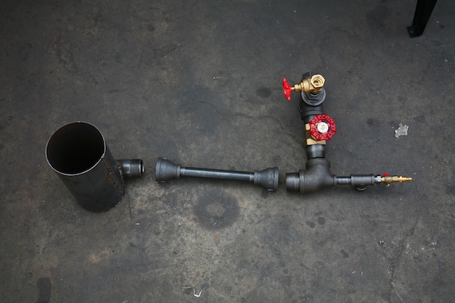
4. Ejector Venturi Assembly and Swirl Burner
-Assemble the ejector venturi assembly as shown. Be sure to tape the threads.
-The cross of the assembly screws directly on top of the filter housing.
-Attach the swirl burner to the end of the ejector assembly.


5. Manometer
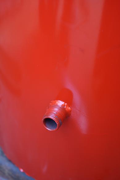
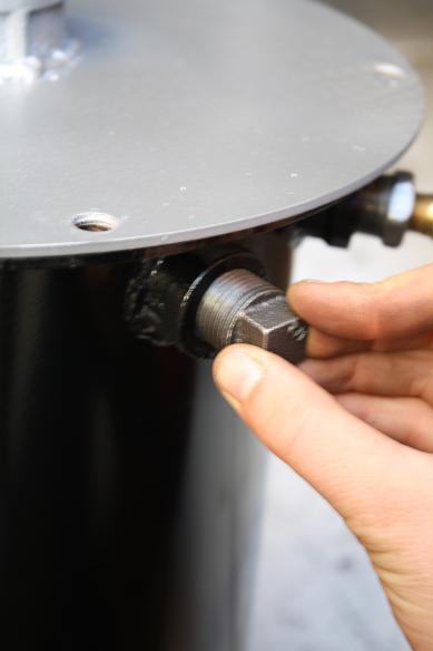
- Locate the 1/2 inch male nipple that is welded onto the outside of the cowling. This will be considered the front of the GEK.
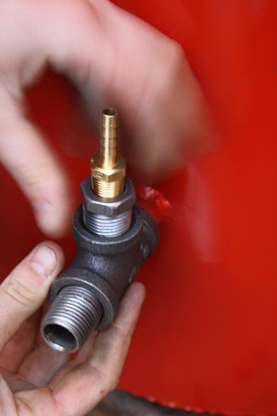
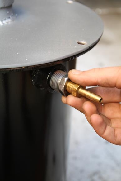
- Thread on the 1/2" tee, (see image below) screw in 1/2 close nipple at the end of the tee.
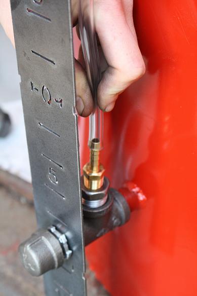
- Screw in the 1/2 inch to 3/4 reducer on the top of the tee, put 1/4" brass barb in reducer.
- Place the manometer face plate onto the close nipple and let the top of its bracket lay underneath the flange of the gas cowling. The 5/16 bolt that holds the reactor to the gas cowling will also hold in place the bracket of the manometer at this point. Do not put the bracket of the manometer in between the reactor and the gas cowling's flanges. This will cause leaking.
- Thread the lock nut on to the 1/2" close nipple in cowling, and place a black cap on to the end . This port can also be amended to use for a thermocouple. A thermocouple in this port will clear the bottom of the reactor and a temperature reading at the bottom of the reduction bell can be taken from this point.
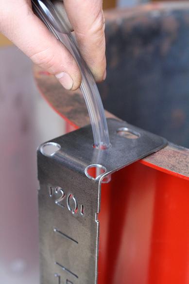
- Insert one of the clear tubes into the middle hole of the manometer bracket, feed it down through to the brass barb at the bottom.
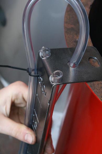
- The other end of the clear tube will follow along the front of the manometer face plate, loop at the bottom, and its end will barely poke up through the hole on the left. This is the reactor pressure manometer.
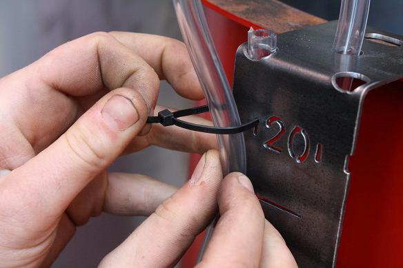
- Loop the zip tie through the manometer and around both parts of the clear tube, one piece in front and one behind.
- The filter manometer will be on the right. Start with the tip at the right hole on the manometer face plate bracket, feed it down behind the manometer, create a loop at the bottom and bring it up in front of the manometer face plate. Secure with zip ties, as before.
- Thread in the 1/2 inch to 3/4 inch reducer into one of the ports at the top of the filter housing (there are two). Thread in the brass barb into the reducer. The long end of the tube for the filter manometer connects to this brass barb.
- Notice that there are two more ports on the filter housing. Place two plugs into these ports. These two extra ports can be used for gas sampling, wet scrubbing and recycling systems, temperature, or pressure ports.


Comments (0)
You don't have permission to comment on this page.