return to How to Build and Run the GEK Gasifier
The instructions below explain how to do the final assembly for the v2.0 GEK Level IV kit. The instructions assume you have the fully welded and painted GEK kit in your possession, either through purchasing it as a Level IV kit, or building it yourself. If you need to weld together the raw sheetmetal and accessory parts kit (Level II or III), please go to the full fabrication instructions.
The individual pictures below can also be found as a photo gallery here
There are seven components that we will be assembling:
- Gas Cowling
- Downdraft Reactor Insert
- Cyclone
- Pack Bed Filter
- Axial Fan
- Swirl Burner
- Fuel Hopper
The gas cowling, reactor and hopper bolt together into a single vertical assembly. The cyclone, packed bed filter and blower similarly bolt together into a single vertical assembly. These two assemblies attach together via the gas outlet flange to the cyclone. A soft hose attaches the blower to the swirl burner.
All these parts are pictured below. This is what you should have received with the Level IV kit, or built via your own effots.

While assembling the various vessels, be sure to remember these common standards used throughout the GEK kit.
-All metal to metal flange connections require clay weather strippings two rows thick, as air tight sealant.
-When tightening bolts follow same pattern as tightnening lug nuts on your car. Stagger tightening, dont go around in order. This will
keep a good air tight seal.
Gas Cowling assembly
-Turn Cowling upside down. Slide legs over posts, tighten set screws. (second pictures shows older designs with nuts welded to the gas cowling
and legs bolted to these nuts.)


- While its upside down, Pull off two rows of weather stripping. lay onto cowling around cicumference
of ash port hole, on the inside of the bolts. Screw on wing nuts, hand tight.
-Turn upright.


- Remove turning handle from ash grate, and slide ash grate into cowling, grate side up. Make sure
1.5" nipple fits through coupling in bottom of the cowling.
-Reach under cowling and screw on turning handle.


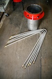
Downdraft Reactor insert assembly
- Turn insert upside down
- Tighten one gas line into elbow coupling.
- Bend clockwise, around the outside of the next coupling, continue around to the second coupling
then bend down and start wrapping clock wise and down around insert. Keep wrapping until its
obvious which attachment it goes to in the mid flange.
- Bend a 90 degree angle about four or five inches from the end of the gas line and screw it onto the
attached coupling.
- Repeat process until all five gas lines are installed.
- Make sure not to overlap lines, they should all fit without crossing.
- Turn reactor right side up.


- Install 1/2" by 6" long Pipe Nipples
- Screw in 1/2" Pipe Nipples into threaded couples inside the reactor insert on the bottom plate.

- Put two lines of weather stripping around the circumference of the 6" hole in the bottom plate.
- Put reduction bell inside reactor on top of weather stripping.
- Place washers and nuts on bolts. tighten.


GEK Alert!
There has been a bit of confusion about the correct height for setting the nozzles. The spacer dimensions described below may or may not result in a correct nozzle height, depending on which GEK version you have. Here's an improved drawing and description with the correct nozzle height. Once you understand the correct height, use the instructions below to do the install accordingly.
- Place a ring of weather stripping around the base of the pipe nipple.
- Slide one inch section of 1" pipe down and push into weather stripping.
- Place another ring of weather stripping on top of 1" pipe section.
- Rub a piece of weather strip into threads at the top of the pipe nipple, this will help secure air inlet
nozzles.
- Slide air inlet nozzles over pipe nipples and push into ring of weather stripping.
- Orientat nozzle so it points in between adjacent two nozzles. Once all installed, they will make a
five sided star, all pointing to the center of the reduction bell opening.


- Assemble Reactor Insert and Gas Cowling
- Pull off two rows of weather stripping, lay onto flange at top of cowling, in between bolt holes and
inner circumference of flange. Press lightly to get it to stick.
- Slide Reactor Insert into Gas Cowling.
- Align Reactor Insert and the Gas Cowlings bolt holes so that the Lighting Inlet is at the front of the
Gas Cowling. It will line up with the 1/2" close nipple in the Cowling.
- Tighten nuts and bolts around flange.
- Put cap on 1/2" nipple instrumentation port in gas cowling
- Put 1" plug in lighting port


Cyclone and Pack Bed Filter
- Attach Cyclone to Gas Cowling
- Place weather stripping around square flange on Gas Cowling.
- Hold Cyclone up so that both square flanges match, install nuts and bolts. Tighten.


- Put plate with 1" close nipple into mason jar lid ring, nipple up.
- Screw onto jar.
- Screw into 1" coupling at bottom of Cyclone.
GEK Alert!
We now suggest using grains of charcoal for the media in the packed bed filter. Charcoal is a much better performing filter media than the included steel wool. See here for directions on changing to charcoal for the filter.
- Place Filter Mesh Plate in bottom of Filter
- Fluff Steel Wool, and pack into filter.
- Place Mesh Plate on top of steel wool to hold it in place
- Screw Filter onto 2" coupling at the top of Cyclone.


Axial Fan
- Place weather stripping on inner circumference of top ring on Filter.
- Arrange Fan so large opening is on top of Fan housing, align bolts to fit so that the fan blows out to the
right.
- Place weather stripping on circumference of Fan Housing.


- Assemble Fan motor and Rotor
- Slide rubber washer onto Motor shaft.
- Screw one nut onto each of the mounting bolts on the Fan Motor, screw it far enough back so the bolt
can go through the lid plate.
- Place Motor shaft through center hole in Fan lid plate. The rubber washer and the motor housing should be
tight against the lid plate and the mounting bolts should fit through the two surrounding holes.
- Screw on the remaining two nuts, on the back side of the lid where the mounting bolts protrude.
- Back tighten the first set of nuts to lock Fan motor into place.


- Put Fan Rotor on shaft collar blades side out, so the set screw aligns with the flat side of the shaft collar.
- Tighten set screw to secure fan rotor.
- Place this entire assembly, motor side up, onto the Fan housing, aligning bolt holes to fit over bolts on housing.
- Tighten nuts.


Wiring for fan motors labelled: FASCO 12V (#2807-510-176):

Swirl Burner
- Attach female coupling on the 2" tube to the 2" close nipple on fan housing.
- Tighten 1/2" by 8" pipe nipple to 1.5" to 1/2" bushing. Screw this assembly into 1.5" coupling at end of 2" hose.
- Insert 8" pipe nipple into 2" pipe on Swirl burner.


Fuel Hopper
- Place two rows of weather stripping around inner circumference of top ring of Reactor insert.
- Put a layer of the foam window sealant on top of existing rubber seal on drum lid.
- There are four holes in the hopper 8" down from the top. Insert 5/16 by 1 1/4" bolt from the inside of the Hopper so they stick out
on the outside.
- Put on a lock washer then a nut. this will secure the bolt in the side of the hopper.
- Bend a hook in the straight end of the included springs. The round spring loop is held in place with the side bolt and nut. The hook end goes over the lip of
the lid.


Comments (4)
Ken Boak said
at 12:18 pm on Jan 17, 2009
Jim,
When installing the vertical 1" air pipes, is there an additional 1" long section of 1" pipe to raise the nozzles by the same height - i.e. a nozzle height adjustment spacer?
Please clarify
Ken
jim mason said
at 12:32 pm on Jan 17, 2009
yes, the 1" long spacers go below the regular nozzle risers. this is so that you can lower the nozzles from the standard height without having to cut off the nozzle risers. the combination of the two should put the nozzles about 3" above the restriction. be sure to seal both the joints in the risers with the clay provided.
given what we are learning about the increased combustion speed with the preheated air, i think this height will eventually prove to be too high. thus i've made it easy to lower. narrowing the nozzle ring is also likely called for. that can be done by screwing reducer bells onto the street 90s used for the regular nozzles.
the particulars of optimizing this geometry are not yet known. i deliver it with a default known to work reasonably, but i am certain it can be improved. and as we figure that out, we'll incorporate the learning into what we deliver as the default.
jim
Ken Boak said
at 5:58 am on Jan 19, 2009
Thanks Jim,
- I'll have to cut these from a piece of 1" tube I found in my scrap bin.
I'm looking for advice over the manometer,
What are your preferred tapping points?
What pressure difference do you typically obtain?
Ken
Ken Boak said
at 6:06 am on Jan 19, 2009
Jim,
OK I found the answer to the manometer configuration on the GEK website. Pictures of set-up are very clear.
http://www.allpowerlabs.org/gasification/gek/images/v2.0/v2.0gallerynewmanometer.html
Ken
You don't have permission to comment on this page.